

Disclaimer
Note that in the following blog I make comments about the Diamond hot end, E3D’s Titan extruders, and Duet electronics and maybe some other organisations. I wish to make it clear that I have no affiliation with any of these companies. All the items mentioned were bought by me as a paying customer and any comments I make are my own personal observations. None of what follows should be construed as any sort of recommendation or otherwise.
Introduction
For a while now, I’ve been wondering what the maximum print speed of a Diamond hot end might be. My rationale has been that effectively it has three melt zones (one for each filament) which in theory, if all three were used at the same time, should result in a higher filament melt rate and thus higher possible print speeds.
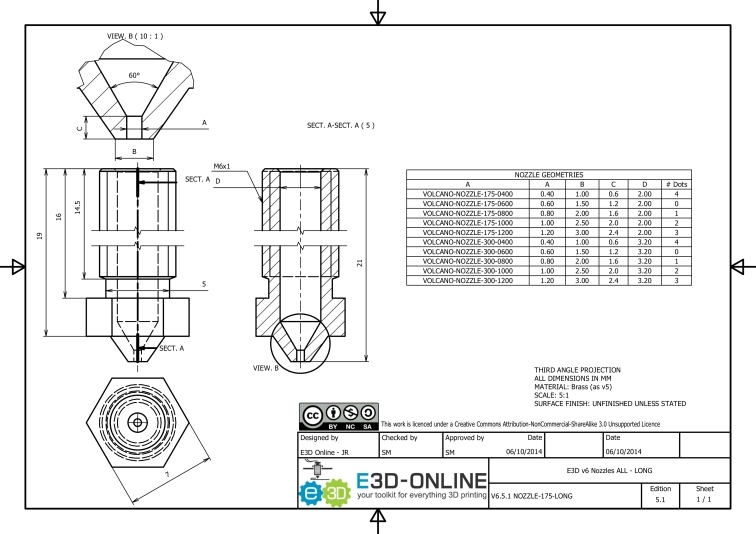
Also, looking at a drawing of the hot end, shows that many of the internal dimensions are very similar to E3D’s Volcano nozzle. Here is a drawing of the Volcano, reproduced here with kind permission from E3D.
Here is a picture of the Diamond hot end, reproduced here with kind permission of RepRap.me.
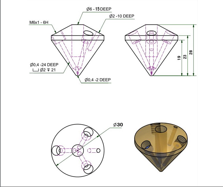
As you can see, the internal dimensions for the filament path are very similar, so possibly the melt rate might be similar too – and of course, there are three of them in a Diamond hot end.
Test Methodology
I guess one way to test the melt rate might be simply to heat the nozzle and extrude filament into air at higher and higher speeds and measure the actual amount of extruded filament each time. However, I wanted to know how that translates to actual attainable print speeds, so I decided to adopt a different strategy and actually print something.
My first consideration was that I needed to know that whatever speed I chose to print at would actually be attained and not limited by acceleration. Also, I wanted to have long continuous moves so that the extrusion wasn’t too affected by stopping and starting. Finally, I wanted to be sure that the first few layers were laid down nicely so that the quality of subsequent layers wasn’t affected by the quality of the underlying layers (this didn’t quite work as planned but more on this later). So this meant that I would have to start slow and gradually increase the speed. With that in mind, I didn’t want something that was big in both X and Y directions as the first few layers would take a long time to lay down.
As readers of this blog will know, my gantry assemblies are heavy. In the X direction it’s about 1,670gms and in Y about 3,048gms. So my accelerations are correspondingly low but X is higher than Y (obviously). (The acceleration figures were derived from calculations of the masses involved and the stepper motor characteristics and verified by testing to ensure that they are attainable without any missed steps).
So, I elected to have an object that was long in X but narrow in Y which would be fairly quick to print the first few layers. I created a simple cuboid 300mm in X, 30mm in Y and 30mm in Z which I sliced using 100% infill at 90 degrees (i.e,. the infill is parallel to the sides). I would simply ignore the short Y moves and concentrate my findings on the longer and faster X moves.
The theoretical speeds are as follows.
X length is 300mm. Acceleration is set to 1200 mm/sec^2. With the initial velocity being zero the formula for maximum speed is sqrt(2*acceleration*length/2) = 600mm/sec (should be adequate)
Y length is 30mm. Acceleration is set to 660 mm/sec^2. Using the same formula, the maximum attainable in speed in Y is 140.7 mm/sec. So regardless of what speed is demanded, that’s as fast as moves in Y will go, and they will ramp up to that speed, then ramp down to zero.
The object was initially sliced at 100mm/sec. I used my “normal” PLA settings which are 195 deg C hot end, 50deg C bed, and with an extrusion multiplier of 95%. I bought three identical reels of PLA from the same vendor and loaded one into each of the extruders. The object was then printed, starting at 50% speed (so 50mm/sec), for the fist few layers. Then the speeds was increased on layer change and the surface finish visually checked for obvious under extrusion or other signs of distress.
A total of four test were carried out. The first was with a (more or less) standard 0.5mm nozzle and single filament input, at 0.3mm layer height. Note that the standard Diamond nozzle is 0.4mm but I always drill mine out to 0.5mm for reasons that I won’t go into here. Note also that I always use the hot end as a mixing hot end. That is to say that I always keep the filament moving in the “unused” inputs. So when printing with a single filament, I load some into the other two inputs and use a mixing ratio of 0.98:0.1:0.1. This means that the “single input” tests were actually using 98% of one input and 1% of each of the other two.
Test number 2 was with the same 0.5mm nozzle and 0.3mm layer height but using all three inputs in more or less equal proportions (actually 34%, 33% and 33%).
Test number 3 was with a 0.9mm nozzle (RepRap.Me will supply one if you ask them), 0.6mm layer height and single input.
Test number 4 was with the 0.9mm nozzle, 0.6mm layer height and all three inputs.
Note that the model was re-sliced at slower speeds for tests 3 and 4.
I recorded a video clip of each step and put it all together, with comments. Note that even though I shortened the video by cutting out many of the intermediate steps, it’s still around 27 minutes in length. Watch it if you can – you’ll be surprised by some of what you see.
Notes and conclusions.
Firstly, it soon became obvious that at higher speeds there was an issue at the end of each move. This was much more obvious on the short 30mm “Y” moves but also noticeable at the end of the longer “X” moves. My theory (which will do until I can think of a better one) is that (at high speeds) pressure builds up between the extruder and the nozzle tip. Then as the carriage approaches the end of it’s travel, it starts to slow down but because of the pressure that has built up, and although the extruder starts to slow down, the filament is still being forced out at the same speed, resulting in over extrusion of filament relative to axis movement. This leads to the raised ridges which are visible in the video at the ends of each move. Duet firmware does have a pressure advance setting but I’ve never experimented with it all that much – perhaps it’s time that I did – watch this space……………..
Secondly, in a similar vein, as the speed was increased, blobs started to appear on the print. Despite my setting seams to “nearest”, Slic3r decided to move the print head diagonally from one corner to the other on layer changes at the end of the “Y” direction infill. This was a long non-print move and the blobs got bigger as the print speed was increased. Again, my theory that it was due to pressure build up would explain it. So, again using pressure advance in the firmware might help.
Thirdly, I had expected to reach a point where the demanded extrusion speed exceeded the melt rate for the filament and that it would be obvious when that speed had been reached. I reality, it wasn’t as clear cut. In general terms the extruded filament just got “thinner” for want of a better word and was less able to cover defects from the previous layer. It seems that the Titan extruders do too good a job of pushing the filament through. No clicking (apart from the last test), no skipped steps, no grinding of filament – nothing! In some of the tests, there is clear evidence that the maximum speed at which filament can be laid down has been exceeded but it is fair to say that some under extrusion probably started at some speed before this.
Fourthly, my somewhat arbitrary observations of maximum melt rates are as follows:-
With a 0.5mm nozzle and 0.3mm layer height, the maximum print speed before severe signs of under extrusion occurred was 160mm/sec. To calculate the maximum melt rate I used nozzle area (0.0558125mm^2) x the layer height (0.3mm) x the speed (160mm/sec) x the extrusion multiplier (0.95) giving me 8.955 mm^3/sec.
With a 0.5mm nozzle, 0.3mm layer height and using all three filament inputs, the maximum print speed before severe under extrusion was observed was 260mm/sec (honestly! ……. watch the video if you don’t believe me) giving a calculated melt rate of 14.551 mm^3/sec.
With a 0.9mm nozzle, 0.6mm layer height and single filament feed, the maximum print speed was 62 mm/sec. Using the same formula for melt rate calculation, nozzle area is 0.381753 mm^2 x layer height (0.6mm) x speed (62) = 22.485 mm^3/sec.
The final test using a 0.9mm nozzle, 0.6mm layer height and all three inputs was much harder to estimate the point where severe under extrusion occurred. In the end I decided on 90mm/sec (180% of 50mm/sec) based solely on the fact that at higher speeds, “clicking” from the extruders was clearly audible. This gives a calculate melt rate of 32.640 mm^3/sec.
Whether my somewhat arbitrary choice of maximum speeds or whether some lower speed would be more realistic, I leave up to each reader to come to their own conclusions. Personally, I think that the Diamond hot end is capable of some fairly substantial melt rates, possibly comparable to an E3D Volcano (at least when being fed by three extruders), but as I’ve never used a Volcano, I cannot say for sure.
What is fairly convincing is that using all three inputs results in higher melt rates and thus higher speeds. Also, a 0.9 mm diameter Diamond hot end can maintain a larger volume flow rate than a 0.5mm nozzle, even when the smaller nozzle is being fed with all three inputs.
I hope readers will have found something of interest in the above. (Does anyone have a use for several 300mm x 30mm x various thickness plastic sticks?)
Ian
PS. The featured image is a still from the video. Did it really reach 300mm/sec? Time to reach 300mm/sec at 1200 mm/sec^2 (Vf-Vi/a) = 300/1200 = 0.25 secs. Distance to get up to 300mm/sec (s=1/2at^2) = 37.5mm. So yes, it was accelerating for 37.5mm, and decelerating at the end for 37.5mm so for the 225mm in the middle it really was doing 300mm/sec.
PPS – Some more calculations (as of 23rd June).
Looking again at the drawing of the Diamond, we see that there is a tube about 21mm long and 2mm diameter. Given that the filament is 1.75mm diameter it’s difficult to estimate the filament to metal contact area, so difficult to estimate what contribution this section will make to the overall melt rate. However, taking the shorter 0.4mm “tubes” there is a 3mm long part and then another 2mm long part giving a total area of about 6.3mm^2 for a single filament – using three inputs we have 3 x 3mm plus 2mm giving a total area of 13.8 mm^2. If we open those holes up to 0.9 mm, the area for a single filament becomes 14.1 mm^2 and for all three, 31.1mm^2.

That doesnt look like 170 mm/sec to me.
LikeLike
Sorry which part doesn’t look like 170mm/sec? I think I explained that the short front to back “Y” moves are limited by acceleration to a maximum of 140mm/sec. That is to say that at an acceleration of 660mm/sec^2, the maximum speed that can be attained over a distance of 30mm is sqrt(2*acceleration *length/2) = 140.7mm/sec. So those short moves will accelerate from rest up to 140.7mm/sec over 15mm then decelerate down to zero fro the remaining 15mm. For the long 300mm X move, the acceleration is 1200mm/sec^2 and using the same formula, the maximum theoretical speed is 600mm/sec. To reach 170mm/sec the time take is t=(Vf-Vi)/a = 0.142 secs and the distance travelled is (s=1/2at^2) =12.042mm. So it will be accelerating for about 12mm, and decelerating for about 12 mm at the end. Therefore for (300-24) 276mm it will be travelling at 170mm/sec.
LikeLike
I think its the x movements i’m referring to.
LikeLike
Yes so as I explained, the first 12 mm and the last 12 mm will be the acceleration and deceleration phases. The 276mm in the middle is at 170mm/sec. I double checked the speeds by using the frame rate of the video which was shot at 1080/50p and it came out very close to what the theory said was happening. You can also check with a stop watch. There is a section at the end of the video at 300mm/sec and the length of the X move is 300mm so the acceleration phase of that move is 37.5 mm and 0.25 seconds. Therefore, the acceleration and deceleration phases take 0.5 seconds. The constant speed section is (300-37.5*2) 225mm which at 300mm/sec takes 0.75 seconds so the total move time is 0.75+0.5 = 1.25 seconds. So watch the video, start the stop watch at the beginning of the move and stop it at the end. It should be close to 1.25 seconds. You can do the same with the 170mm/sec move if you do the maths.
LikeLike
it seems like you have the math down very well and methodical testing, leaving no room for dispute.
LikeLike
Yes I think so. I didn’t set out to prove anything other than to see if it’s possible to print at higher speeds using all three inputs of a Diamond hot end. I have say I was a bit surprised to see just how fast it would go before I ran into under extrusion, that’s why I doubled checked everything. I doubt if I’ll every print anything for real at those sort of speeds, but it was interesting to see what might be possible.
LikeLike