

I’ve been intrigued by the silicone “sock” that E3D make for their hot ends. I’ve recently been using their “Edge” filament which has a great affinity for sticking to the nozzle and E3D claim that using a silicone sock helps to keep the nozzle clean. The other potential advantage that I see is for situations where the print cooling fan blows air across the nozzle which can drop the temperature. This may in itself not be enough to affect the print but in recent versions of Duet firmware, it can trigger a heater fault. For safety reasons, if the firmware sees a sudden drop in temperature, it will turn turn the hot end heater off because it could well be caused by the heater cartridge coming out of the hot end.
In my particular case, the fan ducts are arranged so as to deflect the print cooling air down and away from the nozzle. However, it is practically impossible to prevent cooling air being deflected back up to the nozzle off of the bed or the printed part. As a quick test, I heated the nozzle to 195 deg C then, with the bed 100 mm below the nozzle, turned the fans on at 100%. There was no discernable drop in temperature. I then repeated the test but with the bed only 1 mm below the nozzle and noted a 2.1 deg C drop in temperature. Not bad but not desirable.
Searching the internet I couldn’t find any “off the shelf” insulating “socks” for the Diamond hot end so decided to have a go at making my own. The result was quite successful. Here is how I went about it :-
Firstly I designed the mould. I’ll put the stl and OpenScad files on Thingiverse and add a link at the end of this post. Here is picture of the OpenScad design.
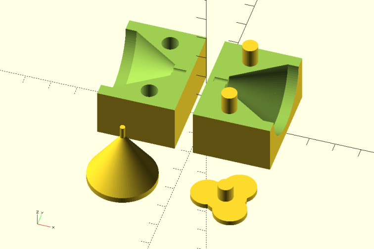
There are 4 parts to it. The cone shaped part is the same size as the Diamond hot end with a small locating pin added to the tip. This cone has a hole in it which takes the “clover shaped” part. This is to make clearance around the heat sinks but leave a lip for the sock that will go over the top of the brass nozzle. I’m still refining this “inner top” part so by the time I get to put it on Thingiverse, it may look a bit different. The two parts together form the inner section. I had to do it this way so that it could be printed. The other two parts go together and form the outer part of the mould. This outer part makes the shape of the Diamond but 2mm bigger all round.
Here are the printed parts.
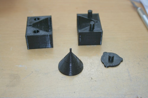
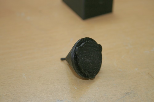
As I said, the “inner top” is still evolving. Here is the inner section assembled. They don’t need glueing together – in fact it’s probably best not to.
I didn’t do anything special about smoothing the parts. I printed them using a 0.5mm nozzle with 0.3mm layer height and just gave them a bit of a rub over with some fine abrasive paper. I guess a smaller layer height and better finish would make it easier to get the sock out of the mould but it wasn’t a huge problem with the release agent I used (see below).
What is important is that the parts fit together well. I just stuck the two outer parts together with sticky tape but an elastic band would work too. Once the two out parts are (temporarily) held together, the inner cone shaped part should be tested for fit. The top of the inner should be flush with the top of the outer. If it’s higher, check that the locating “pin” on the bottom of the cone is going fully into the recess in the outer mould.
I know absolutely nothing about all the various mould making materials. I did a bit of research and settled on using this stuff.
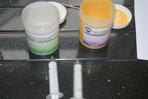
It’s called “High Temperature Moulding Rubber” or “RTV High Temperature Resistance Mould Making Rubber” by DWR Plastics. I bought it off Ebay but you can buy direct https://www.dwrplastics.com/product-information/5389e00cc0a0e/RTV-High-Temperature-Resistance-Mould-Making-Rubber-250g-Kit.
It’s claimed to be good for up to 330 deg C. There are many other brands of this stuff around, any of which will probably work. The reason I chose this particular one was that it seemed east to mix – simply use the same volume of each part A and part B.
The next step was to coat the mould parts in release agent to prevent the RTV from sticking to it. I’ve seen a couple of YouTube videos where people use hot Vaseline and other such things but I decided to buy the release agent from the same source (DWR plastics).
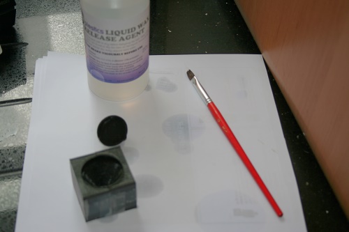
Shake well and cover all of the inner parts, including the top. Then cover the inside and top of the out parts. Allow to dry and give apply a second coat. I actually applied a third coat as well.
Next I assembled the inner part into the outer parts, filled a syringe with water, then filled the mould. It takes around 5ml. So that’s how much rubber you’ll need to mix. Actually, it’s difficult to get it all out of whatever container you mix it in, so mix a little more – say 6 or 7 ml.
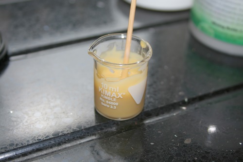
I happen to have a few 10 ml syringes laying around (no I’m not a junky but I do use e-cigs and mix my own “juice”). So I used two of these and managed to “suck” 3ml of each of the two compounds and squirt them into a small glass container. This stuff is really thick and “gloopy” so you need a large hole in the syringe – i.e. don’t fit any sort of needle to it.
Then mix thoroughly – a cocktail stick works well.
The next step is to pour the stuff into the mould
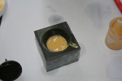
Then insert the inner part which will push the rubber up the sides. Make sure the inner part goes in all the way so that the top is flush with the mould. Then centre it by eye.
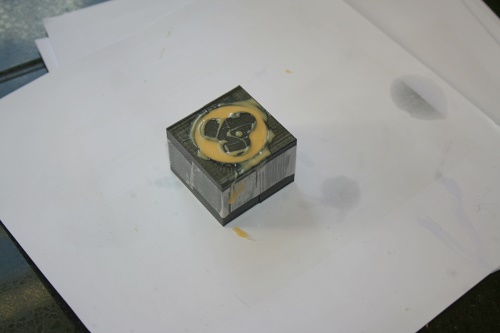
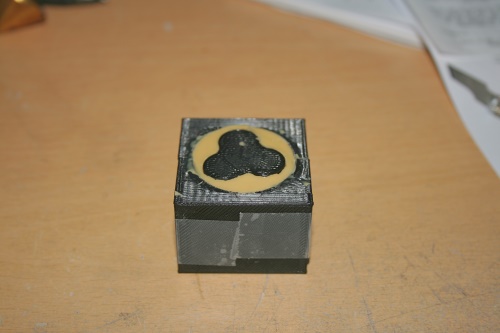
Scrape off any excess or top up as necessary then leave it to set. The cure time is stated as being 1 to 2 hours at 25 deg C. I left mine a little longer – just to be sure.
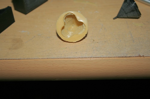
Once it has cured, use a sharp modelling knife to clean up the top.
Then, carefully cut around the “clover leaf” top, down 2mm to the top of the cone proper. I did the same around the outer edge. Then remove the adhesive tape and pull the out mould apart.
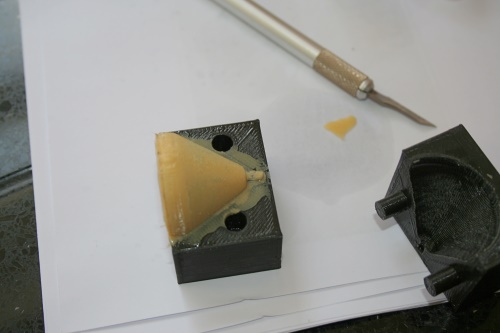
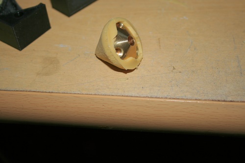
It might feel a bit stiff but I found going around the joint with the modelling knife helped but be careful not to cut into the rubber boot. Once a small gap has appeared, insert a small flat blade screwdriver and twist. Keep working around the edge and it’ll come apart.
Once one half of the mould is off, it’s quite easy to pull the rest out of the second half.
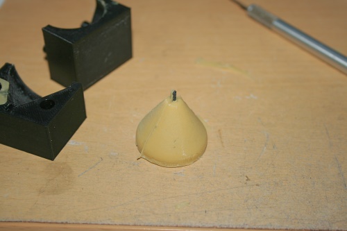
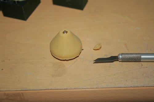
The next step is to remove the inner. This is surprising easy. Simply roll it down like this …..
…. and you’ll end up with this……….
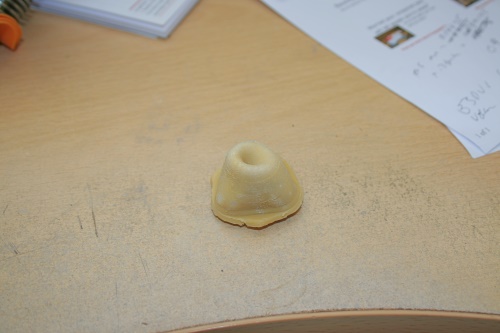
…………which is inside out so turn it the right way out and you get this………
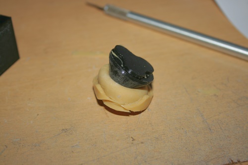
Here it is fitted to a nozzle. It is important that moulded rubber is pushed up onto the brass nozzle as far as it will go. Keep going around the nozzle using your thumb to push it up.
So what remains is to carefully cut around the base of the mould to expose the tip of the nozzle, like this.
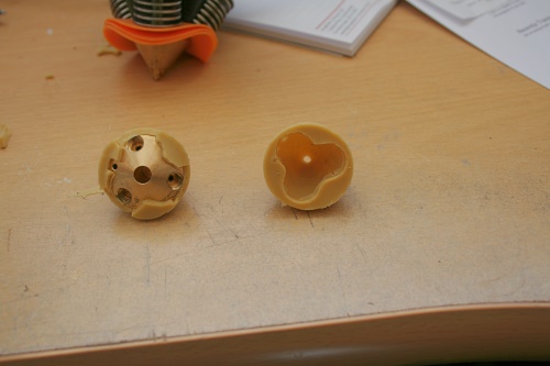
Now in reality, I found fitting it to be a pain because of the 3 layers of heat break insulation around the heat sinks so I had to cut chunks away and even then, disassemble the heat sinks. Here is what I had to do (on the left)
So, I said at the outset that the inner top part was still evolving and that is why. I have modified the design so hopefully it will be possible to fit the sock without any cutting and hopefully without having to disassemble the heat sinks. The parts are designed, I just have to print them and make another casting.
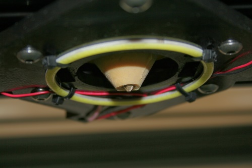
Here is a picture of it installed on my machine
I’ve done very limited testing so haven’t all that much to say at the moment but here is what I have so far.
Without the sock, the time taken to reach 195deg C from a starting temperature of about 29 deg C was about 225 seconds. With the sock fitted, the time is about 200 seconds. I haven’t measure the cool down time as it’s unimportant to me, but it seems to take much much longer.
Without the sock and with the print bed at 1mm from the nozzle tip, putting the print cooling fans on at 100 % gave a 2.1 degree drop in hot end temperature before it recovered. With the sock fitted, there is no discernable change in temperature with respect to the operation of the print cooling fans.
There is no gain in maximum attainable print speed. That is to say, the filament melt rate is unchanged which is as I would expect, because there will be no increase in temperature in the melt zone of the hot end. Proof of this and some other stuff related to print speeds will be the subject of my next post.
Link to Thingiverse files here https://www.thingiverse.com/thing:2386473
Ian
