
Further to my original post, I have found some inconsistency in results. I had written earlier that my thoughts were that the required purge amount was somehow related to print speed. My suspicion was that there is more molten filament in the melt chamber and above, (before the heat break) when printing at low speed compared to higher speeds. I also said that I needed to do more testing to confirm this.
I have now done that testing and can now confirm that this is not the case and the cause is something else – more later.
Firstly, I should explain my test methodology. I have designed a test piece which is a cube, 60mm x 60mm x 3mm thick. This cube has two rectangular cut-outs, 15mm wide x 40mm long spaced 10mm from each edge and with 10mm between them. This part forms one stl file and is all one colour. Then there are two rectangular shapes which fit into these cut-outs, each one being a separate stl file which is assigned a different colour.
This combined object was sliced in Slic3r. The post-processing script was then run on the gcode file with purge amounts from 2.0 to 4.0 in 0.5 mm steps giving me 5 new files, each with different tool change positions. Each one was then printed with all other print settings the same.
Here is a picture which shows them all.
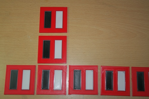
From left to right, they are with 2.0mm purge, 2.5, 3.0,3.5 and 4.0. Ignore the two upper prints for now. If you look very closely, 2.5mm is the optimum. At 3.0 mm you can just see some bleeding creeping in to the upper right corner of the white rectangle. This is where it changed to black filament just a fraction too early. The same is noticeable on the lower left corner of the black rectangle but this has some red creeping in and does not show very well in the photograph.
Here is a close up picture of what 4mm purge looks like.
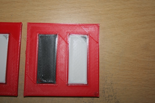
Please ignore the overall print quality. These we all printed at 90mm/sec and I did not pay any particular attention to the first layer height. From this picture, it is very clear when the purge amount is too much. You can see some black in the top right corner of the white rectangle and maybe a slight smudging in the bottom right hand corner of the red rectangle. Depending on how good your screen is, you might also be able to see the red smudge on the lower left corner of the black rectangle.
This next picture is a close up of what I deem to be the optimum.
This is with 2.5mm of purge which is the maximum that doesn’t lead to smudging due to the tool change being premature. If you look very closely you’ll see why this isn’t a perfect technique. The left hand edge of the outline of the black square is grey, rather than black and the bottom edge and part of the right hand edge of the white rectangle is dark grey rather than white. This is the transition period from one colour to another and short of using a some sort of a wipe or prime tower, this is a good as it gets.
Once I had established the optimum purge amount, I then printed the same file at lower speeds to investigate the issue that I had observed and laid theses prints out in the same column. So going back to the first picture, the print immediately above the horizontal row was printed at 50% speed (about 45mm/sec) and the one above that was printed extremely slowly at 20% speed (about 18mm/sec).
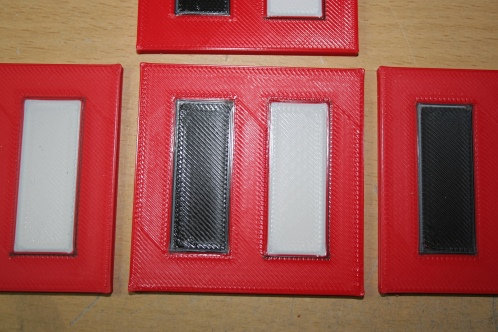
Here is a close up of 2.5mm purge but at 20% speed. 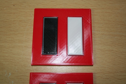
As you can see, in terms of the purge amount, it is unaffected by print speed. Looking closely, you can still see the light grey on the top and left hand edge of the black rectangle, and the dark grey on the bottom and right hand edge of the white rectangle. As I mentioned above, this is the transition period from one colour to another and short of using a some sort of a wipe or prime tower, this is a good as it gets. Personally, I don’t think it’s bad. Whether it is good enough depends on people’s expectations and the criteria that the final, printed object has to meet.
So, what was my cause for concern? It was printing an object that consisted of a lot of small parts. The nature of the object was that it had to be printed much slower than I normally print and so, when I observed that something wasn’t right with the colour changes, I assumed it was to do with the lower speed. I have now proven that this is not the case. Further analysis of the post processed gcode file for that object shows that there is an error (at least one) in my python script. Basically, it won’t move a tool change further back than the original position of the tool change that came before it. So, if the amount of filament to be extruded between tool changes is less than the amount needed to purge the hot end, it won’t work. I need to address this or (more likely) take a different approach and re-write the script.
So for now, the script works where there is a reasonable amount of filament extruded between tool changes but cannot cope with tool changes that are too close together.

Very interesting subject Ian. My new build is not printing as of yet but I am interested in learning the capabilities of multi-color printing. Your tests are helpful reading as I begin to appreciate more the complexity of what will be involved when that day arrives. I also enjoyed your previous post on bed flatness and leveling issues. This is the kind of information people like myself who are just getting started need to know. Thanks and keep up the good work.
LikeLike
Thanks for the feedback Terry. It’s nice to know that I’m not completely wasting my time. Ian
LikeLike
Not wasting your time at all Ian. I’m sure there are many following along with great interest. You’ve certainly made me consider the advantages of a mixing hot end again. Great work and many thanks for sharing!
LikeLike
Thanks for the feedback James. I’ll persevere a bit longer and see how things pan out. Ian
LikeLike
You’re not Deckingman. I’m sure there are other people like me ‘monitoring’ your progress quietly simply because we don’t have anything to add for the moment! Keep up the good work !
Gilles
LikeLike
My feeling is, and I think I mentioned this earlier, that it matters what colour your are switching from. I found that black takes a lot longer to be cleared. But then I do not have a mixing head. So the volume is much larger.
LikeLike
Hi Lykle. I think we had this conversation on a forum somewhere but maybe you didn’t read my reply. Switching filaments on a mixing hot end is nothing like completely changing from one filament to another. Remember that (in the case of the Diamond hot end) all 3 filaments are loaded at all times so the only purging to be done is that small portion of filament which is in the mixing chamber. In the pictures above, I’m not actually seeing any difference in the required purge between black to white, black to red, red to black, red to white, white to black or white to red. Ian
LikeLike
Hi Ian,
Nice train of thought!
I would be very interested to see the code you produced so far. I realised the problem you mentioned about the distance between tool changes possibly being too small, but that should be easy to prevent in the py code.
I’m more used to programming in PHP, but should be able to read and execute python code with a bit of effort.
I think your reasoning is sound enough. I setup my diamond hotend with slic3r, and the parts that come out look reasonable enough so far. I disabled retraction between tool changes, so now if I feed a color file to the printer the colors are not where you would expect them but further “down the line” obviously.
LikeLike
Hi Josh,
You need to see the later update that I posted. I found a few bugs in the script and the thing I suspected about distance between tool changes being too small wasn’t actually the issue. In theory, it shouldn’t matter how much filament is extruded between tool changes. That is to say, if we move all the tool changes backwards by the equivalent of say 2mm of filament extrusion, it shouldn’t matter if there is only 1mm between too changes. For that 1mm we are shifting both the start point and the end point if you get what I mean. The script still has one or two issues tat I haven’t had chance to look at. It’d be much easier if the gcode file was just a series of “XYE” commands but there are things like Feed rate commands with no move so I can end up with a segmented move either side of speed change which gets interesting. As I have said, I’m not much good at writing code and it really needs a professional to sort it out properly. My original post has the annotated script so you should be able to follow the logic (but beware, there are bugs).
Ian
LikeLike