This is a copy of a post I did as guest on Think3dPrint3d ‘s blog back in December 2016. Now that I have my own blog up and running, I thought I’d post it here as well, just to keep all my posts together in one place.
I have been using a Diamond hotend (3 inputs and one output) on my custom built CoreXY printer, controlled by the DuetWifi for some time now. This blog post is documentation on how to setup the DuetWifi with a Diamond hotend however it can be generalized to other multiple input – single output hotends. They might use different configurations but the principles will be the same. I have taken the definition of a mixing hot end as one which has multiple filament inputs and a single output (nozzle), although see the “issues with mixing” section at the end.
Hardware requirements.
Assuming you have the necessary number of extruders for your particular hot end, you will need to be able to drive them all. The new Duet WiFi and the older Duet v0.8.5 both have support for 2 extruders. If you have 3 or more extruders, then you will need to procure an expansion board or use another method to connect additional stepper drivers to the Duet expansion connector.
Important note. A mixing hot end must have filament loaded into all inputs at all times. Failure to do this will mean that extruded filament will find it’s way up into any unused inputs where it will cool and solidify causing a blockage which will be very difficult to clear.
Software and Firmware requirements.
You should have a slicer that is capable of supporting multi part objects. Although some things can be done by post processing the gcode file, objects which share the same Z position, would be very difficult to deal with using this method. Also, the slicer and the printer firmware should ideally be capable of supporting firmware retraction (G10) – more on this later. At the time of writing, Slic3r (version 1.2.9) is known to support these features. David’s (DC42) branch of RepRapFirmware supports firmware retraction as of version 1.10.
Some slicers support multiple extruders but not necessarily multicoloured objects (although there may be workarounds). It is often possible to use different extruders (tools) for perimeters or infill or support materials.
Connections.
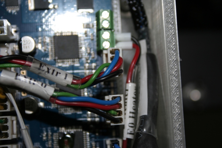
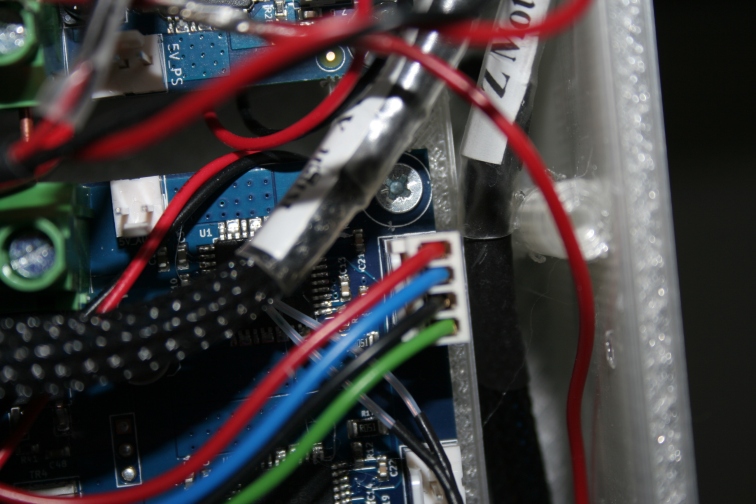
Refer to the Duet wiring diagrams and connect the first extruder motor to E0, the second to E1 and any others to the relevant connectors on the expansion board. I highly recommend that you put a label on each extruder at this time to act as a reminder of which is which when you come to load filament. Remember that by default, the first extruder drive is referred to extruder 0(zero) not 1. This may initially confuse you when you start using slic3r which refers to the first extruder as “1” not rather than “0”. I believe that the latest version of Duet firmware does allow you to “remap” extruders (tools) so that the numbering system start with 1. (See reference to M563 S1 later in this post). New users might want to adopt that approach but i have become accustomed to using the 2 different numbering systems so personally, I’ll stick with it.
Extruders 1 and 2 connected to the main Duet WiFi boardExtruder 2 connected to the Duex5 expansion board
A mixing hot end will only have one heater so connect this to the first heater (marked E0). Similarly, connect the thermistor to the first thermistor connector (also E0). It’s not strictly necessary to use these exact connections but if you decide to use some other terminals on the Duet board, make a note of what you have connected to where. Finally connect the hot end cooling fan to wherever you prefer. The most common configuration is to connect the fan to one of the “always on” terminals but my fan is very high air flow and so quite noisy. Therefore I prefer to have it connected to one of the PWM fan terminals and run it in thermostatic mode so that it only comes on when the hot end is above 45deg C.
Configuration settings – tool definitions.
The first thing to do is define the tools. To do this, it is necessary to edit the confg.g file. The way I prefer to this is to keep a copy of all the sd card files on my PC where I can maintain back up copies. So I would edit the config.g file on my PC then upload it to the Duet through the web interface. One could also physically remove the sd card, pop it into a card reader and copy the file across. Another way to do it is to edit the file directly, either through having the card in a card reader or via the system editor in the web interface. This is the quickest way to do it but of course this means that you have no backup copy.
There are a few different ways that you can define the tools. You will probably need a tool for each of the “solid” colours. That is to say, tools which will only use 100% of one filament. Then you will need a tool or tools that combine different filaments in various proportions.
So to define a tool which uses only one colour, it is only necessary to set which extruder and which heater it will use. The gcode to define a tool is M563. So for the first 3 tools you could use something like this;
M563 P0 D0 H1
M563 P1 D1 H1
M563 P2 D2 H1
This would define the first 3 tools (P0 to P2) to each use one of the extruders (D0 to D2) but the same heater (H1).
IMPORTANT. Be aware that Slic3r and perhaps other slicers, may use a different numbering system and the first tool is defined as 1 not 0. This can be easily rectified by either defining tools starting with tool 1 and up, or by using the M563 S1 command in config.g to tell the firmware to add a 1 to every tools number
If we want to mix filaments, we’d need create more tools and turn on mixing. So, we might have another tool defined like so;
M563 P3 D0:1:2 H1 ; Define tool 3 (P3) to use all three extruders (D0:1:2) and heater 1
M568 P3 S1 ; Enable mixing for tool 3
M567 P3 E0.34:0.33:0.33 ; Set mixing ratio for tool 3.
What this does is to define the tool T3 to use all 3 extruders (D0:1:2) then it uses M568 to enable mixing for that tool. Finally, it sets the mixing ratio using M567. In this case roughly the same quantity of each of the 3 filaments. However, this mixing ratio should always add up to 1. So, I’ve used 0.34 of extruder 0, and 0.33 of extruders 1 and 2 (0.34+0.33+0.33 = 1.00).
We could also have other tools. Say for example we had Red filament in extruder 0 and Yellow in extruder 1, we could define another tool which would blend equal amounts of the tool to create Orange. It would look like this:
M563 P4 D0:1:2 H1 ; Define tool 4 (P4) to use all three extruders (D0:1:2) and heater 1
M568 P4 S1 ; Enable mixing for tool 4
M567 P4 E0.5:0.50:0.00 ; Set mixing ratio for tool 4.
Of course, we can define as many tools as we like. The upper limit of tool numbers is constrained only by the Duet’s free memory so over 400 tools are possible on the DuetWifi.
Managing a large number of tools would become cumbersome though and there is another way. Once a tool has been defined to use all the extruders and mixing has been enabled, we can simply change the mixing ratio before or during the print. It can be done before the print commences by putting the mixing ratio into the start gcode file. It can also be done during a print by entering the required M567 command in the web interface or by post processing the gcode file that the slicer generates. In theory the tool mix ratio can be set differently for each gcode move.
So we can simply have one tool which is defined as a mixing tool. In practice, this won’t work with slicers which expect different tools for different (coloured) parts of an object. So, I have found the best compromise is to just define 4 tools (or one more than the number of extruders), one for each of the primary filaments and one which is a combination of all three. Coincidentally, in slic3r, if you set your printer to have 3 extruders, it will give you 4 tools to choose from for any object.
Taking this a step further, it is still useful to be able to use any combination of filaments for any tool. For example I could have red green and blue filaments loaded but want to print with Cyan, Magenta and Yellow. So all of my tools are defined as mixing tools but the first three use 100% of only one filament (actually this is not strictly true but we need to consider retraction before I elaborate more). Then if I subsequently want to change a tool to use a different filament or combination of filaments, I can do so but simply changing the mixing ratio at the start of the gcode file, without having to bother with all the other configuration settings. It can also be done “on the fly” from the web interface. This can also be used if one wanted to print a number of copies of the same object but in different colours. Simply slice the object once, then edit the start of the gcode file to change the mixing ratio and/or tool number.
Here is what the tool configuration part of a config.G file might look like.
; Tools
M563 P0 D0:1:2 H1 ; Define tool 0
G10 P0 X0 Y0 ; Set tool 0 axis offsets
G10 P0 R0 S0 ; Set initial tool 0 active and standby temperatures to 0C
M568 P0 S1 ; Enable mixing for tool 0
M567 P0 E1:0:0 ; Set mixing ratios for tool 0
M563 P1 D0:1:2 H1 ; Define tool 1
G10 P1 X0 Y0 ; Set tool 1 axis offsets
G10 P1 R0 S0 ; Set initial tool 1 active and standby temperatures to 0C
M568 P1 S1 ; Enable mixing for tool 1
M567 P1 E0:1:0 ; Set mixing ratios for tool 1
M563 P2 D0:1:2 H1 ; Define tool 2
G10 P2 X0 Y0 ; Set tool 2 axis offsets
G10 P2 R0 S0 ; Set initial tool 2 active and standby temperatures to 0C
M568 P2 S1 ; Enable mixing for tool 2
M567 P2 E0:0:1 ; Set mixing ratios for tool 2
M563 P3 D0:1:2 H1 ; Define tool 3
G10 P3 X0 Y0 ; Set tool 3 axis offsets
G10 P3 R0 S0 ; Set initial tool 3 active and standby temperatures to 0C
M568 P3 S1 ; Enable mixing for tool 3
M567 P3 E0.34:0.33:0.33 ; Set mixing ratios for tool 3
This is not quite how I have my tools defined but to understand the reason for that, we need to look at extruder retraction which is discussed later in this document.
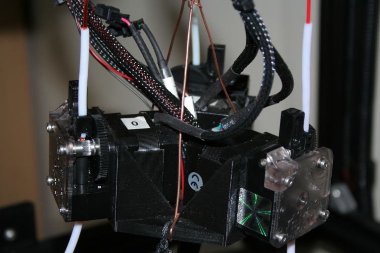
The 3 E3D Titan extruders suspended centrally above the bed in a sort of counter balance “flying” arrangement
Tool offsets
You will notice that in the above tool definitions, there is no X or Y offset, or more precisely the X and Y offsets are set to zero (G10 Pn X0 Y0). That is because there is only one nozzle. X and Y offsets are only necessary where there are more than one nozzle and where they are physically offset from each other. Theoretically these offsets should default to zero but I always like to set them to zero, just in case something should get changed in firmware which might affect the default settings.
Heating and standby temperatures.
You will also notice that in the tool definitions above, the initial active and standby temperatures are set to zero (G10 Pn R0 S0). That is because I don’t want the hot end to start heating whenever a tool is selected. Instead, I have the heating and standby temperatures set in my start gcode where I can also put the specific temperature as needed for a specific filament.
With a mixing hot end, we only have one heater and one nozzle so if we are using the same type of filament in all 3 inputs, we can instantly switch between tools without having for the next one to warm up, or the previous one to cool down. Therefore, we can (should) set the tool active and standby temperatures to the same values.
This is what I have in my start gcode for PLA in all 3 inputs.
G10 P0 S195 R195 ; Set tool 0 operating and standby temperatures
G10 P1 S195 R195 ; Set tool 1 operating and standby temperatures
G10 P2 S195 R195 ; Set tool 2 operating and standby temperatures
G10 P3 S195 R195 ; Set tool 3 operating and standby temperatures
Then when the print runs and a tool change is needed it can be instantly switched with no warm up or cool down delay.
Obviously, if we had different types of filament in one or more of the extruders, we would need to change these values for those extruders (tools).
Extruder retraction.
With “normal” retraction, only the “active” extruder will retract. That is to say that if we are only pushing one filament into a mixing nozzle, normal retraction will only pull that single filament back. In effect, all that happens is that filament is drawn from the unused inputs rather than from the nozzle tip. In practice, this is just like having no retraction at all.
What is needed is for all filaments to be retracted, regardless of whether they are actively in use or not. Fortunately Duet hardware and firmware give us the ability to accomplish this. It is done by using firmware retraction using the codes G10 (retract) and G11 (unretract). This might be slightly confusing because G10 is also used for tool offsets but without a tool number, it is used for firmware retraction.
G10 is used in conjunction with M207 to define the retraction amount and speed.
Here is what I have in my config.g file.
M207 S1.5 F3000 ;set firmware retraction
S is the amount in mm. F is the Feed rate mm/min (divide by /60 to get mm/sec).
Optionally one could also have R (additional length on unretract) and Z (additional Z lift in mm)
It is vitally important to use this firmware retraction with a mixing hot end so, the slicer software must also be configured to use this. In Slic3r this is simply a matter of ticking a check box which is in the Printer Settings tab under “General”. Whenever retraction is needed, Slic3r will insert a G10 command (and a G11 command to unretract). For other slicers, there is sometimes a facility to post process the gcode output and one could use this to replace whatever retraction codes was output with G10. Another option would be to use some sort of text editor to do a “search and replace”.
Tool Definitions revisited.
Now that we have set our firmware retraction to retract all 3 filaments simultaneously there is another little issue that will become apparent but can be avoided. With a mixing hot end we must have all the inputs loaded with filament at all times otherwise extruded filament will simply find it’s way up into unused inputs where it will cool and solidify. We must also retract all filaments simultaneously for reasons discussed above. Therefore, when we print using just a single filament and extruder for a prolonged period of time, what happens is that on the unused inputs, the same piece of filament is constantly being retracted and unretracted. Eventually it will just get worn away and will cease to move and retraction stops working and our prints get stringy.
There is also another possibly even more important issue, which is that most filaments will degrade if reheated and cooled a number of times which is what will happen if we primarily use just a single filament for an extended period of time. I’ve seen with PLA that if it is left in the mixing chamber too long without being extruded, it gets completely cooked and when it comes time to extrude the first few millimetres come out as a mixture of liquid and vapour.
There are a couple of things which can help. The first one is, before starting a print heat the nozzle and extrude some filament from each of the extruders. This will ensure that there is a fresh piece of filament in each of the extruders which may well last for enough retract and unretract cycles without getting so worn that it fails to move.
The way that I prefer to do it is to define the tools so that every tool always uses the main filament plus a small proportion of all of the other filaments. In theory, one might think that this would result in muddy and muddled colours. In practice, it is hardly noticeable and it uses the main filament but just enough of the other inputs to keep them moving so that retraction isn’t always moving the same piece of filament back and forth and the same piece of filament isn’t being constantly reheated and cooled.
Here is what my final tool definition section looks like.
; Tools
M563 P0 D0:1:2 H1 ; Define tool 0
G10 P0 X0 Y0 ; Set tool 0 axis offsets
G10 P0 R0 S0 ; Set initial tool 0 active and standby temperatures to 0C
M568 P0 S1 ; Enable mixing for tool 0
M567 P0 E0.90:0.05:0.05 ; Set mixing ratios for tool 0 (90%,5%,5%)
M563 P1 D0:1:2 H1 ; Define tool 1
G10 P1 X0 Y0 ; Set tool 1 axis offsets
G10 P1 R0 S0 ; Set initial tool 1 active and standby temperatures to 0C
M568 P1 S1 ; Enable mixing for tool 1
M567 P1 E0.05:0.90:0.05 ; Set mixing ratios for tool 1 (5%,90%,5%)
M563 P2 D0:1:2 H1 ; Define tool 2
G10 P2 X0 Y0 ; Set tool 2 axis offsets
G10 P2 R0 S0 ; Set initial tool 2 active and standby temperatures to 0C
M568 P2 S1 ; Enable mixing for tool 2
M567 P2 E0.05:0.05:0.90 ; Set mixing ratios for tool 2 (5%,5%,90%)
M563 P3 D0:1:2 H1 ; Define tool 3
G10 P3 X0 Y0 ; Set tool 3 axis offsets
G10 P3 R0 S0 ; Set initial tool 3 active and standby temperatures to 0C
M568 P3 S1 ; Enable mixing for tool 3
M567 P3 E0.34:0.33:0.33 ; Set mixing ratios for tool 3 (34%,33%,33%)
If it is critical that the finished print has to be a single colour and cannot be mixed with any other colours, and it is going to be a longish print time, I cut a couple of lengths of filament off of the main roll (say about 1 metre). Then I load the main roll into the first extruder and each of the 1 metre lengths into the other two extruders. So, the machine will use 90% of the filament from the main roll and 5% from each of the offcuts, which means that all the filaments in all the inputs will be kept moving enough to prevent any of the problems mentioned above.
These are what my mixing ratios will always default to. If I want to print a 2 or 3 coloured object using “solid” colours with no mixing for each part, then what I tend to do is simply add M567 commands to the start gcode which will override the default values that I set in my config.g file.
i.e. M567 P0 E1.00:0.00:0.00, M567 P1 E0.00:1.00:0.00, M567 P2 E0.00:0.00:1.00.
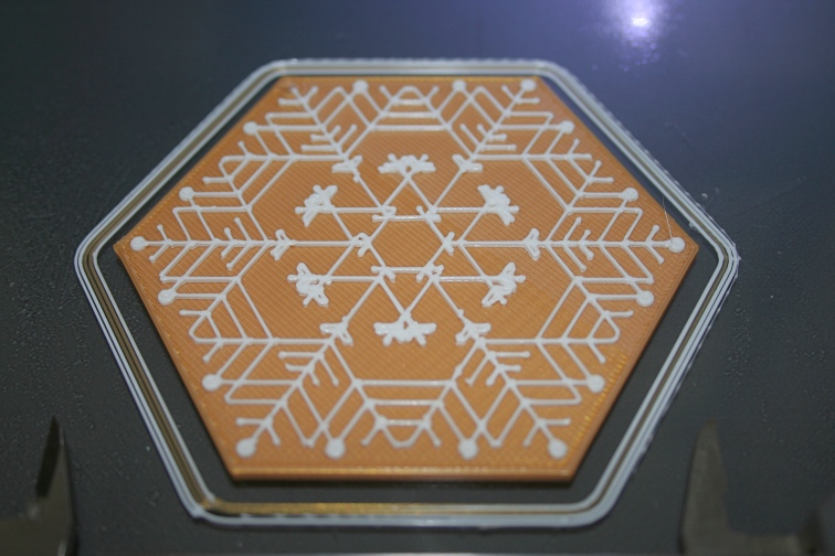
For example the snowflakes were printed with White on Gold. In this case, I had two tools. Tool 1 was 100% Gold, Tool 2″ was 100% White. The base and the flake are separate stls. I added the base (gold part) to Slic3R platter, then in settings set it to use Tool 1. Then I used “Add part” to add the flake and set it to use Tool 2. So, when it printed, the first part of the flake started out Gold until the White filament purged through but that was only about an eighth of the first layer and there are 3 layers of white. Of course, this was all before I had developed the technique for moving tool changes forward in the file detailed here. Multi colour printing without using wipe or prime towers
Two colour print using the Diamond hot end
Tuning and tweaking
With the exception of getting the mixing ratios right for whatever printed outcome is desired, there is very little tuning and tweaking necessary for a mixing hot end compared to a non-mixing hot end. The only thing that springs to mind is that, because we retract all filaments together, the retraction distance can be less.
On my particular machine, with Bowden tubes around 250mm long for PLA at 195 deg C and print speed of around 60mm/sec, retraction of 1.5 mm at 3000mm/min works well.
Of course, using firmware retraction makes setting it up a breeze. Simply print two small cubes spaced about 50 mm or more apart then during the print use Duet Web Control to change the retraction on the fly and observe the difference. Use M207 Sn.n Fnnn where S is the amount in mm and F is the speed (feed rate) in mm/min. Start with a small number and increase it slightly until signs of stringing disappear. Repeat for other materials, print speeds and temperature if necessary but you’ll likely find one value that works well for most situations.
Scripting mixing ratios
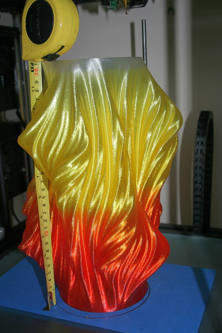
Another way to use a mixing hot end is to post process the gcode file to enter mixing commands at various places. I have a little python script which an M567 command after “n” layer changes. Tony from Think3dPrint3d kindly put it on github for me. It runs through loops, each one progressively decreasing the mixing ratio for one filament and increasing another. So the colour changes throughout the height of the printed object from colour A to colour B, then colour B to colour C. This can be extended to go from C back to A and then the entire sequence repeated. This is how I produced the following objects:
One of my own designs
Big Julia vase design by Virtox on Thingiverse
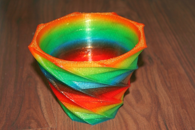
The big Julia vase is printed with Red, Yellow and Clear translucent filaments. Starting at 100% red, reducing the Red by 1% and increased the yellow until 100% Yellow, then repeat going from Yellow to Clear. The mixing is changed at every 5th layer to get one complete iteration over the height of the object. The smaller rainbow Julia vase shown at the beginning of this post used Red, Blue and Yellow and changed the mixing at every layer change so ended up with Red,Purple (Red and Blue), Blue, Green(Blue and Yellow),Yellow, Orange (Yellow and Red) then back to Red and repeat the sequence.
Thoughts and ideas.
Most people think of multi coloured objects but even if your slicer doesn’t support multi part objects it may well support multiple extruders. This means that one could choose to use one extruder for the infill but a different extruder for the perimeters. One could then use an exotic or expensive material on the outside but cheaper “everyday” filament for the inside. Or possibly use a clear filament for the perimeters to give the object a clear coating.
Printing support material using a different extruder is another possibility that springs to mind.
Then there are other exotic materials such as electrically conductive filament. It could be possible to print an electrical circuit within an object.
Issues with mixing.
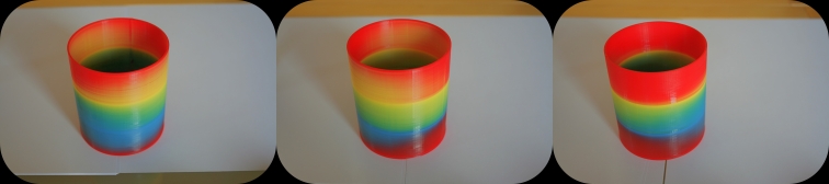
There is a fundamental restriction with the Diamond hot end. This is that there is no mixing chamber as such. The disadvantage is that when filaments are “mixed” they come out of the nozzle like stripy toothpaste. So the colour is biased towards each input. This effect can be partly negated by using translucent filament. Or it can be exploited for decorative purposes. I have printed a 3 sided pyramid with each face a different colour by using a single tool with a mixing ration of 0.34:0.33:0.33 and orientating the pyramid on the build plate such that each face is directly opposite a filament input.
The same pot viewed from3 different angles showing the effect of incomplete mixing
Video
Finally, this is a video of my custom CoreXY printing the large Julia Vase by virtox shown in the picture above:
Hello,
very nice und usefull article. Just one little question. In section tool definition with P3 you mean tool 4 and no 3 right? got me a little confused there
Blimey, it’s 2 years since I wrote that piece so I had to go back and refresh my memory. I can confirm that there are no typos and if you read it again, you’ll understand. Tool numbering can get a little confusing but P3 means tool number 3. The first tool is tool 0, so the second is tool 1, the third tool 2 and the forth is tool 3. It’s the same for drive numbering. The first one is D0, the second D1, etc…
To confuse things even more, the web interface used to refer to drives starting with 1 rather than zero. So on the web interface, drive 1 was actually drive 0, drive 2 was drive 1 etc. It took me a lot of badgering to get that changed but thankfully it’s now as it should be and drive 0 is referred correctly as drive zero on the web interface.
Hello!
i am about to embark on this cruel voyage. your article here gives me hope that this is very possible.
the one question i have is, what about extrusion rates? if i am using say tool 1 and i add/transition to tool 2 would that not mean that i have double the extrusion value? essentially doubling the amount of filament entering the “mixing chamber” and essentially over extruding?
It’s important that the sum of the mixing ratios add up to 1. To get a transition from one colour to another, you use the same tool but vary the mixing ratio.
You can’t use two tools at once but you can define any tool to use multiple extruders. Then you set the mixing ratio for each extruder but the sum of all those ratios must always add up to unity.
Ok, so essentially what your doing is adjusting the extrusion rate of the filament. so 50 50 0 would mean tool 0 and 1 is at 50 percent its max feed rate of filament. im new to all this. so i apologize. so far ive managed to get a duet wifi and a tronxy x5s to work great. i recently picked up a geeetech 301. i bought a duet for that and a smart effector and mag ball setup. but this multi nozzle thing has me intrigued. i just might keep the diamond hot end and see what i can make. the original intention was speed. a fast accurate little delta. but you have made a compelling argument for the diamond with this article.
but in your educated opinion, what do you think would be a better setup for a delta. smart effector with a e3d v6 or the diamond hot end?
You are still confusing tools with extruders. It’s probably because you are thinking of the diamond hot end as a multi-nozzle hot end but it isn’t. It’s a single nozzle but with multiple filament inputs which combine together just before the nozzle.
So no, I don’t mean that with a mixing ration 0.50:0.50:0.00 then each tool is at 50%. What I do mean is that with a mixing ratio of 0.50:0.50:0.00 for a single tool, then two of the extruders will each supply 50% of the filament and the third extruder will supply none.
Personally I wouldn’t contemplate fitting a Diamond hot end to a Delta, although it has been done. I’m no expert on Delta printers but I think they are better suited to light weight hot ends and the Diamond is very heavy. Also, I suspect that the multiple Bowden tubes might play havoc with effector tilt. The smart effector you mentioned is designed to work with an E3D style hot end – adapting that to work with a Diamond will be a difficult, if not impossible task.
Regarding speed. What do want? Something that is capable of moving the print head at high speeds and high accelerations, or something that will print an object in a shorter time? High speeds and high accelerations will allow fast non-print moves but aren’t much use if you can’t melt and extrude filament at the same rate.


Hello,
very nice und usefull article. Just one little question. In section tool definition with P3 you mean tool 4 and no 3 right? got me a little confused there
LikeLike
Blimey, it’s 2 years since I wrote that piece so I had to go back and refresh my memory. I can confirm that there are no typos and if you read it again, you’ll understand. Tool numbering can get a little confusing but P3 means tool number 3. The first tool is tool 0, so the second is tool 1, the third tool 2 and the forth is tool 3. It’s the same for drive numbering. The first one is D0, the second D1, etc…
To confuse things even more, the web interface used to refer to drives starting with 1 rather than zero. So on the web interface, drive 1 was actually drive 0, drive 2 was drive 1 etc. It took me a lot of badgering to get that changed but thankfully it’s now as it should be and drive 0 is referred correctly as drive zero on the web interface.
HTH
Ian
LikeLike
Hello!
i am about to embark on this cruel voyage. your article here gives me hope that this is very possible.
the one question i have is, what about extrusion rates? if i am using say tool 1 and i add/transition to tool 2 would that not mean that i have double the extrusion value? essentially doubling the amount of filament entering the “mixing chamber” and essentially over extruding?
how did you over come this?
Thanks
Ben
LikeLike
Hi Ben,
It’s important that the sum of the mixing ratios add up to 1. To get a transition from one colour to another, you use the same tool but vary the mixing ratio.
You can’t use two tools at once but you can define any tool to use multiple extruders. Then you set the mixing ratio for each extruder but the sum of all those ratios must always add up to unity.
LikeLike
Ok, so essentially what your doing is adjusting the extrusion rate of the filament. so 50 50 0 would mean tool 0 and 1 is at 50 percent its max feed rate of filament. im new to all this. so i apologize. so far ive managed to get a duet wifi and a tronxy x5s to work great. i recently picked up a geeetech 301. i bought a duet for that and a smart effector and mag ball setup. but this multi nozzle thing has me intrigued. i just might keep the diamond hot end and see what i can make. the original intention was speed. a fast accurate little delta. but you have made a compelling argument for the diamond with this article.
but in your educated opinion, what do you think would be a better setup for a delta. smart effector with a e3d v6 or the diamond hot end?
LikeLike
Hi Ben,
You are still confusing tools with extruders. It’s probably because you are thinking of the diamond hot end as a multi-nozzle hot end but it isn’t. It’s a single nozzle but with multiple filament inputs which combine together just before the nozzle.
So no, I don’t mean that with a mixing ration 0.50:0.50:0.00 then each tool is at 50%. What I do mean is that with a mixing ratio of 0.50:0.50:0.00 for a single tool, then two of the extruders will each supply 50% of the filament and the third extruder will supply none.
Personally I wouldn’t contemplate fitting a Diamond hot end to a Delta, although it has been done. I’m no expert on Delta printers but I think they are better suited to light weight hot ends and the Diamond is very heavy. Also, I suspect that the multiple Bowden tubes might play havoc with effector tilt. The smart effector you mentioned is designed to work with an E3D style hot end – adapting that to work with a Diamond will be a difficult, if not impossible task.
Regarding speed. What do want? Something that is capable of moving the print head at high speeds and high accelerations, or something that will print an object in a shorter time? High speeds and high accelerations will allow fast non-print moves but aren’t much use if you can’t melt and extrude filament at the same rate.
LikeLike