

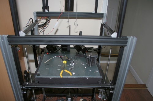
Like many things in life, this printer modification evolved into something much more than my original intention. By way of introduction, this picture shows my original hot end mount and X and Y axes.
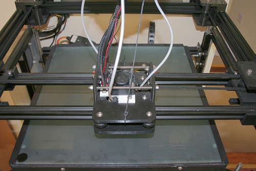
As readers of my blog will know, I use a Diamond mixing hot end. This is a rather ungainly beast with 3 heat sinks sticking out at 28 degrees taking up quite a lot of space and weighing in at around 250gms (excluding any extruders). Because of the weight, the engineer in me decided that the best way to mount it would be to fix it between two parallel rails, rather than having it hanging over the side of a single rail, which is why I ended with a such a huge X carriage. It was heavy too. The X carriage including the hot end weighed 690gms and the Y carriage with the X rails fitted weighed in at 1,210gms so my combined Y axis weight was a whopping 1,900gms. Having said all that, I regular used to print at 90mm/sec with non print moves set to 350mm/sec with accelerations set to 1200mm/sec^2 and the thing was absolutely rock solid. It was impossible by hand, to “flex” the hot end in any way.
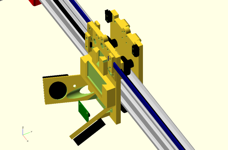
My issue was that I have another Diamond hot end, fully assembled but with a 0.9mm nozzle that I intend to use with Taulman T glass filament, and changing the hot end was a complete pain. So I set out to make a new mount that would enable me to quickly swap hot ends, preferably without the need to use any tools. I also decided to abandon the dual X rail setup and replace the two 2020 extrusions with a single 2040 extrusion. Part of me still thinks this was bad idea from a rigidity point of view, but there are other benefits such as weight savings and increased range of movement which I hope will outweigh the negatives.The next two pictures are Open Scad images of the new X carriage.
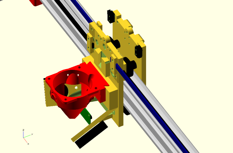
The red part is the new Diamond hot end mount. Effectively, the mount has a sort of Dovetail slot around the two sides and the bottom, into which the mount slides.This is a close up of the actual Diamond hot end mount.
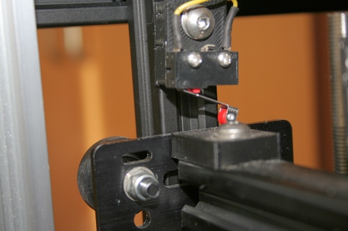
At this point, I realised that I could solve another minor issue that I had. That is, I use an IR mini height sensor but I also use 3DLac on my my glass build plate, and the 3DLac can alter the reflectivity of the glass, meaning that I often had to make adjustments to my Z axis homing. The other problem I have with the IR sensor is that, because of the shape of the Diamond hot end, it is very difficult to mount it anywhere close to the nozzle.So I thought, rather than locking the hot end into place, I could hold it against it’s seat using springs which would allow it to slide up and down. I could then mount the height sensor above the hot end, rather than below it. This would mean that the hot end is itself the height probe. In the event, I discovered a Metrol positioning switch with a claimed repeatability of 0.005mm and decided to use that above the mount but retain the mini IR sensor below the mount if the sliding arrangement doesn’t work out. I’ll cover the Metrol switch in a separate post.
It took me a few attempts to print the parts such that they would slide easily but at the same time have no “wobble”. It wasn’t too hard though because the bottom of the mount is also a “Dovetail” shape and when the springs act down on the mount, the effect is to pull the two faces together.
Of course, I have reservations about how well these plastic printed parts will last over time but I am optimistic because now that I have installed and set it all up, I have only 0.8mm of movement before the switch triggers and can probably reduce this further. The worst case scenario is that if the sliding\probing\homing aspect proves to be unreliable, I will change the design slightly to clamp the hot end in place and go back to using the mini IR probe for homing.
At least I will be able to quickly change hot ends without using any tools. Here is a little video I made showing how that all works.
As with all these things, the update was much more involved than I first though. The entire upper section of the printer has to be disassembled, including the motor mounts, idlers, and of course the X and Y rails………
………but I got it all put back together.
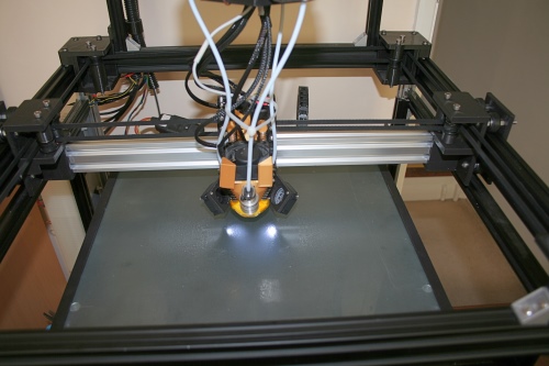
So in practice, what happens for Z homing is that the bed rises, the nozzle touches the glass then the mount gets lifted off it’s seat and slides up until the switch triggers (currently 0.8mm) and my configuration file is set so that Z=0 is 0.8mm below the point where the switch triggers. The switch has 2mm of plunger travel but triggers at 0.3mm so there is a further 1.7mm of plunger travel available. I made use of this by building in a fail safe which is just a micro switch acting on the bed and set to trigger an emergency stop at 1mm after the point where the homing switch should trigger.
If using the nozzle itself as a means of Z homing proves to be unreliable, I have still achieved my original objective which was to have a means of quickly swapping hot ends. As a bonus, I have gained an extra 50 mm of movement in X (now 375 mm instead of 325 mm) and 30mm in Y (now 350mm instead of 320 mm). Also, the new X carriage weighs 520gms instead of 690gms and the new Y axis (without X) weighs 820gms instead of 1,210gms giving me a total weight saving in Y of 560gms ( 1,340gms instead of 1,900gms).
The downside is that I can now “flex” the nozzle in the Y direction if I push and pull hard enough, whereas the old design was rock solid. However, I’ve just finished my first print and there is no sign of and “banding” that I would expect to see if the nozzle was moving around during a print. Also, the Z homing is working like a charm and thus far, is consistent and repeatable.
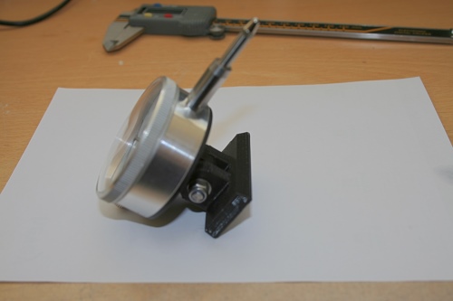
One last thought. With this mounting arrangement, I could fairly easily change to a completely different design of hot end, by making a suitable adaptor. By way of illustration. here is an adaptor that I’ve just made so that I can fit a dial gauge to level the bed.
I’ll give an update in a few weeks or months when I am able to asses how reliable and/or repeatable this turns out to be.
Ian
Late edit. I’ve just finished printing this object which is 133mm tall.
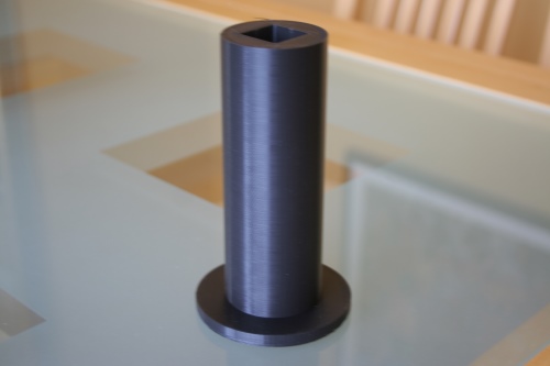
There is no sign of banding and the dimensional accuracy is pretty good. The smaller diameter should be 45mm and it measures at between 45.3 and 45.2 throughout the height. The inner square should be 21mm and measures at between 20.96 and 21.02 and the overall height measure at 132.8mm now that it’s cooled. So although it is possible to flex the hot end in the Y direction by applying force by hand, I’m reasonably confident that there is no movement during normal printing (at least in the centre of the bed).

Very helpful Ian. Thanks for publishing your 3D print adventures. I’ll likely try the 5mm threaded Metrol switch for my similar nozzle probe design using a Cyclops hotend. Look forward to your write up on the digital switch. Thanks…
LikeLike